
Enterprise Architect version 15.2

![]()
My Profile
Help
Hot Topics
Top Community Contributors
Social Media Channels
![]()
![]()
![]()
![]()

doug rosenberg
doug rosenberg
Parallel Agile, Inc. (Founder, Chief Technology Officer) - formerly ICONIX (CEO)Design Driven Testing: Acceptance Testing - Expanding Use Cases using Structured Scenarios
In "test driven" approaches to development, unit testing often gets most of the attention. However, unit testing is generally most useful in discovering "errors of Commission" (more poetically, "whoops, I coded that wrong"). Unit testing is of much less help in discovering "errors of Omission" (more poetically, "whoops, I didn't think of that"). In general errors of Omission are much trickier to detect, and there is very little automated support for detecting them. We worked very closely with the development team at Sparx as they developed the "use case thread expander", and it brings a very unique and useful capability to the industry.
As you read this chapter, make sure you don't miss the discussion at the end of the chapter called "And the moral of the story is..." where we describe some actual "errors of Omission" that were caught and fixed before the release of our mapping software using these acceptance testing techniques, and how fixing these errors improved the user experience.
Design Driven Testing (Sample Chapter): Design of a Java/Flex hotel mapping (GIS) application
My new book Design Driven Testing (co-authored with Matt Stephens) addresses both unit testing by developers and acceptance testing, performed by an independent QA organization. Somewhat uniquely, the book features a real production system as it's teaching example. A worldwide interactive hotel mapping (GIS) application, designed with ICONIX Process, built using Java, Flex, and the ESRI ArcGIS Server mapping software, that we call "mapplet 2.0", which is in production use on the VResorts.com travel website.
This sample chapter presents the full ICONIX Process design of the mapplet project, starting from functional requirements and use cases, all the way down to reverse engineered class diagrams from the final code. One of the unique virtues of using a production example as a teaching example in a book like DDT, is that it's possible for readers to look at the use cases in the attached chapter, and then compare them to the released software as deployed on VResorts.com.

Next month I'll be posting another sample chapter from the DDT book which describes the scenario testing we did before releasing the software and some very real improvements that were made to the usability of the final product as a result. If you'd like to work through the design and testing of mapplet 2.0 with me, in person, our Hands On ICONIX Process open enrollment classes give you exactly that opportunity. In addition to 1 day modules on Business Process Modeling, Service Oriented Architectures, and Embedded Systems Development using SysML, we'll be working through this example for 2 of the 5 day lab sessions.
Also, between now and the end of the year, anyone who orders Design Driven Testing directly from ICONIX will get a free copy of Agile Development with ICONIX Process.
Business Process Modeling with Structured Scenarios
This article (which actually represents the third incarnation of the ICONIX Business Modeling Roadmap), leverages two new capabilities from Sparx Systems, now available in Enterprise Architect. These are the Structured Scenario Editor and the Business Rule Composer. The article describes how these two quantum leaps in technology combine synergistically to enable a new process by combining business process modeling with behavioral code generation for business rules.
eBook: Modeling Service Oriented Architectures
This E-book presents a practical approach to modeling Service-Oriented Architecture solutions from concept to code. The author helps us to understand key SOA concepts and demystifies the "acronym soup" surrounding service-oriented development. Using an illustrated example, the reader is guided through the 'hands-on' ICONIX Process Roadmap for Service-Oriented Architecture. Each step of the roadmap is brought to life using Enterprise Architect Business and Software Engineering edition to derive concrete deliverables from visual models.
Topics include: business rules identification, generating web service interfaces from visual models, BPEL engineering and behavioral code generation.
The eBook is accompanied by an "SOA Project Template" EA model.

The SOA Project Template model contains our SOA Roadmap, a pre-fabricated project package structure, and a Car Rental example which includes:
- a Domain Model
- a WSDL package
- a BPMN model
- example of BPEL code generation from the BPMN model
- a Rule Flow diagram containing Rule Tasks for use with the Business Rule Composer and Behavioral Code Generation
ICONIX now offers JumpStart training on the process described in this eBook, details are available at http://www.iconixsw.com/soajumpstart.html

Four Principles of Agile Triage
There’s an epidemic of bad software floating around these days. Chances are you’ve encountered buggy and/or unnecessarily hard to use software recently.
This epidemic isn’t really surprising, especially if you’ve read the books I’ve written with Matt Stephens: Design Driven Testing or Extreme Programming Refactored or Agile Development with ICONIX Process. There’s a bunch of agile development shops out there underspecifying their software and (as a result) testing it inadequately, so that you and I can have the privilege of debugging it for them and putting new user stories onto their backlog.
Imagine for a moment that you’re working at a company where the agile development process has gone off the rails and there is a train wreck. There’s a lot of smoke from the burndown charts burning up. Bodies are strewn all around, there are broken bones and people are bleeding everywhere. Some parts of your code are savable, and some have to be thrown away. You need to triage the situation and do damage control. Here are some guiding principles for your triage effort:
1. You can’t unit test what you forgot to remember.
2. You can't do scenario testing without modeling scenarios
3. You can't do requirement testing without modeling requirements
4. Excessive timeboxing results in shoddy workmanship
eBook: Embedded Systems Development using SysML
Embedded Systems Development using SysML is not just an overview of the SysML modeling notation - it is a practical guide for systems engineers! The book provides a well defined approach to systems development, and applies it to a detailed example Audio Player system.

In this e-book, author Doug Rosenberg introduces a new roadmap for embedded systems development – ICONIX Process for Embedded Systems.
Each step of the process roadmap is clearly explained, and illustrated by example, using Sam Mancarella's Audio Player model constructed in the Systems Engineering edition of Enterprise Architect.
Topics covered in the e-book include SysML modeling concepts such as requirements, block definition, system behaviour, parametrics, state charts and software implementation, as well as advanced capabilities of Enterprise Architect's Systems Engineering edition including built-in simulation, along with state-machine-driven code generation in VHDL, Verilog, and System C.
eBook: 20 Terabytes A Night
Describes experiences and lessons-learned from the Large Synoptic Survey Telescope (LSST) project. The sheer size and complex nature of LSST, bring a unique set of challenges and a massive software modeling endeavor. UML and ICONIX process are critically important in such an undertaking. Includes an in-depth discussion of tailoring ICONIX Process to support algorithmically-intensive development.

In its first month of operation, the LSST will see more of the Universe than all previous telescopes
combined. Its rapid‐fire, 3 billion pixel digital camera will open a movie‐like window on objects that
change or move; its superb images will enable mapping the cosmos in 3D as never before.
Surveying the entire sky every few days, LSST will provide data in real time to both astronomers and
the public.
The Data Management (DM) part of the LSST software is a beast of a project. LSST will deal with
unprecedented data volumes. The telescope’s camera will produce a stream of individual images
that are each 3.2 billion pixels, with a new image coming along every couple of minutes.
In essence, the LSST sky survey will produce a 10 year “sky movie”.
For LSST Data Management, a good strategy is to make extensive use of rapid prototyping (in this
case algorithm development via prototyping) in addition to UML modeling. So a two‐pronged
strategy of prototyping and modeling has been underway on LSST for a few years now.
A further complication in modeling LSST’s DM software is that the development is being done in
multiple, independent, geographically distributed research organizations—places like Princeton,
Stanford, University of Washington and Caltech, among others. This places some significant
requirements on the modeling tools that are used by the project.
ICONIX Process for Service-Oriented Architecture - A roadmap for SOA development w/ web services
Doug Rosenberg, ICONIX
Figure 1 - A “Secret Decoder Ring” may be required for Service Oriented Acronyms
Trying to make sense out of the “acronym-scrabble” that engulfs Service Oriented Architectures (SOA) is a major challenge. We’re going to take a shot at it in this article by defining a process roadmap and following a single example all the way from architecture to code. Along the way we’ll illustrate many of the key features of Enterprise Architect Business and Software Engineering Edition.
The example we’ll follow will be a Service-Oriented Architecture (SOA) car rental system model, developed by the team at Sparx Systems, that’s implemented with a combination of web-services and custom software. Our SOA Process Roadmap will tie everything together in what we hope will be a clear and understandable manner.
Why a Service-Oriented Architecture Roadmap?
Web services and SOA have become increasingly important in today’s IT universe. A recent article from IBM Global Technology Services[1] suggests that nearly half the companies in the world are either adopting, piloting, or considering SOA, and that investments in these projects may reach between $18 Billion and $160 Billion in the near future. With those sorts of numbers, it stands to reason that many readers will be interested in a roadmap and a cohesive example that brings some clarity to the problem. Hopefully this includes you.
A Quick Introduction to SOA
Service-Oriented Architecture (SOA) is an approach to building complex software systems from a set of reusable services that obey service-orientation principles. Many people believe that Service Oriented Architectures can help businesses to be more “agile” -- in other words, enable faster and more cost-effective responses to changing conditions.
SOA enables construction of applications from fairly large chunks of reusable functionality that can built quickly, primarily from existing services. Thus, SOA promotes reuse at a “macro” level, and, in theory, as an organization publishes more and more business functionality as services over time, the cost of building applications that use those services decreases.
A service that obeys the principles of service-orientation is an autonomous, loosely coupled, and stateless unit of functionality that is made available by a formally defined interface. The functionality provided by a service is discoverable by applications that use the service.
Services are not allowed to call other services, but may communicate with them via messages. That is, services are loosely coupled, and each service implements a single action, such as placing an online rental car reservation.
Services are designed without knowing who will be using them. In a service-oriented architecture, applications are built from services which communicate via messages using a process known as orchestration.
A popular approach to implementing a service-oriented architecture is via web services, which make services accessible over the Internet independent of platforms and programming languages. The BPEL language is often used to orchestrate SOA applications. Building applications from services requires metadata that describes the characteristics of the services, and the data that is used. Typically, XML is typically used describe data, WSDL is used describe the services themselves, and SOAP (Simple Object Access Protocol) describes communication between services.
As it turns out, an SOA example also serves to illustrate many of the features of the Sparx Systems solution, which supports building “executable business processes” that use WSDL (Web Service Definition Language) to implement their solution. And, since projects don’t live by web services alone, Enterprise Architect has numerous other useful features for handling those parts of the application that require custom (non-web service) development. In particular we’ll be spending a significant amount of time exploring in this book include a new and unique capability for “behavioral code generation” for the enforcement of Business Rules, and tight integration with IDEs, including Eclipse and Visual Studio. We’ve leveraged the power of these capabilities into our SOA Roadmap.
The SOA Roadmap (aka ICONIX Process for SOA Development)
As with all of our ICONIX Process Roadmaps[2], our SOA roadmap is defined as a set of activity diagrams. In this case, the roadmap provides a “cookbook” set of steps that can be followed for building systems that are based around a Service-Oriented Architecture.
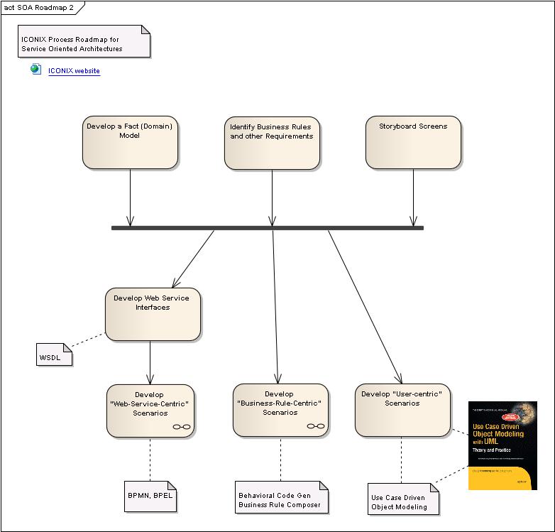
Figure 2 – ICONIX Process Roadmap for Service-Oriented Architecture Development
Figure 2 shows our top-level roadmap. Some of these top-level activities will expand out to a child diagram showing further detail. As you can see, the top-level roadmap includes some “common stuff” like figuring out your requirements and modeling the problem domain, and then provides multiple paths for developing different flavors of business processes, all the way to code.
Getting Ready for SOA
As shown in our top-level roadmap, there are a few “setup” activities that will are necessary at the beginning of our SOA project. We’ll begin with a simple domain model (also called a fact model), that shows the main objects in the problem domain (Figure 3).
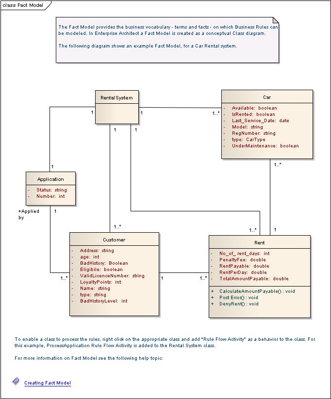
Figure 3 – Domain Model (also called Fact Model) for the Car Rental System
As you can see, the domain model establishes the vocabulary we use to describe our system, and shows relationships between objects in the problem domain. In most cases these relationships include UML generalization and aggregation relationships (not shown here).
Business Rules are represented in Enterprise Architect as stereotyped Requirements. Figure 4 shows a Requirement Diagram for our Car Rental System that organizes these business rules according to different RuleTasks. We’ll talk more about RuleTasks (actions that enforce Business Rules) shortly.
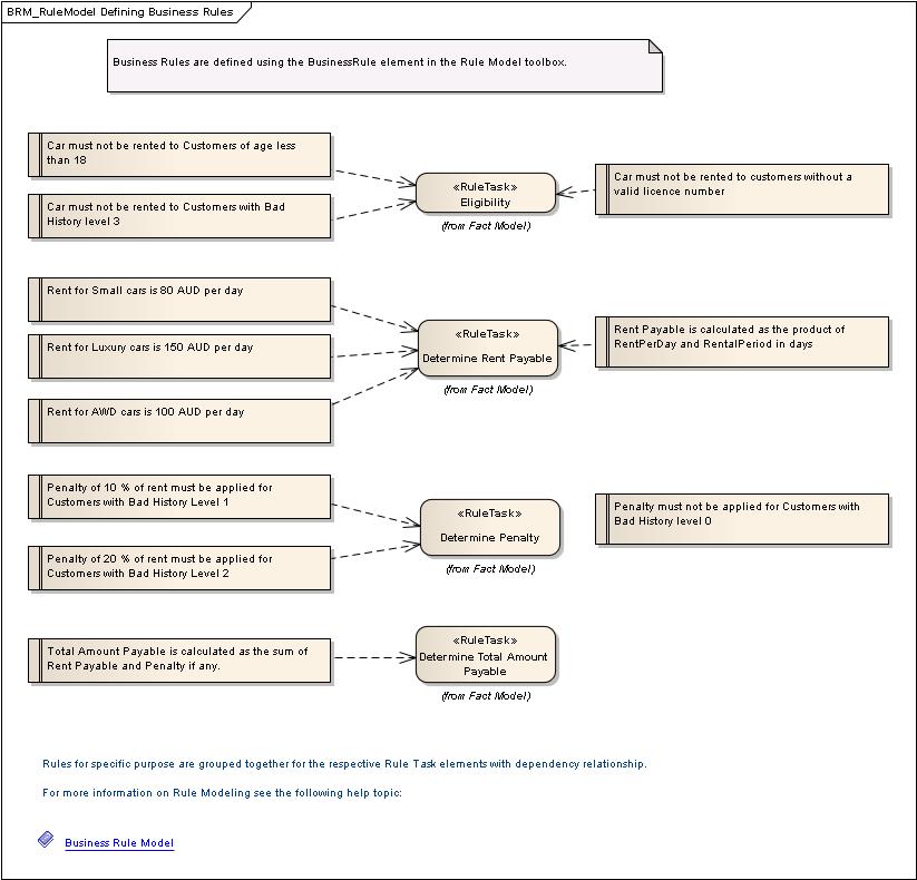
Figure 4 – Business Rules for the Car Rental System, organized by RuleTask
The top-level roadmap shown in Figure 2 reflects the philosophy that when you set out to implement a system using a service-oriented architecture, there will effectively be a mix of 3 different kinds of scenarios:
1) Scenarios that use web services (for which we will develop web service interfaces using WSDL, and orchestrate the use of those web services using BPMN and BPEL.
2) Scenarios that enforce business rules (for which we will use activity diagrams and the business rule composer)
3) Regular old software use cases (which we won't discuss in this book because we’ve covered it quite thoroughly in my other books)
Most systems will contain a mix of these different types of scenarios.
In many cases (but not all) the "web-service scenarios" will cross Business To Business (B2B) boundaries. For example, a car rental reservation system talking to a credit card company to run a payment transaction is a B2B web-service scenario. Where a business process can be implemented via web services, we follow the branch on the left: web service interface definition using WSDL, and orchestration using BPMN and BPEL.
The "business rule scenarios" are more likely to be within the boundaries of one business, for example, the car rental system enforcing eligibility rules on driver age, credit score, etc. There is little or no user interface in these business rule scenarios, so they can be completely code generated from an activity diagram using the business rule composer. For processes that are primarily focused on enforcing business rules, we take the right branch: Behavioral Code Generation from Activity Diagrams using the Business Rule Composer.
Finally there is the user interface. These would be the screens of the car rental system that the reservations agent accesses, and which would trigger the business rule checks and B2B transactions. These parts of the system are best modeled using use cases, following a “use case driven” approach that’s out of scope for this article, but well documented in my other books[3].
With all of these branches, we can compile and build using either Eclipse or Visual Studio, and use the Sparx “MDG Integration” technology to keep models and code in-synch.
A Short Intro to Web Services and WSDL
Suppose you wrote an interesting application (maybe a program that automatically generated a horoscope based on your birthday and today’s date), and you wanted to publish your application to the Internet so anybody in the world could purchase their horoscope from you. How would you do that? Most likely, you’d do it with a web service.
Web services support distributed, platform-independent development. Using web services, you can publish any application you choose to build over the web. A web service can be written in any language and hosted on any computer that’s connected to the Internet.
The concept behind web services isn’t new; previously developed similar approaches include OMG CORBA, Microsoft DCOM, and Java/RMI. You can think of a web service as something like an Internet-enabled API.
You’d describe your horoscope web service using Web Service Description Language (WSDL); an XML-based language that describes the public interface to the web service. WSDL tells you only how you can interact with the web service; it says nothing about how the web service works internally.
WSDL defines Services as collections of Network Endpoints, or Ports; a collection of Ports defines a Service. A Port associates a network address with a reusable binding, and a Message is an abstract description of the data that is being exchanged. A WSDL file has an “abstract” section that describes Ports and Messages, and a “concrete” section that describes specific instances of their usage. This file structure is shown in Figure 5.
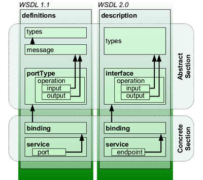
Figure 5 - WSDL file structure showing Abstract and Concrete sections (from Wikipedia[4])
Developing Web Service Interfaces (WSDL) with Enterprise Architect
Before we can use BPMN and BPEL to orchestrate a collaborating group of web services, we first need to be able to define the web services themselves.
WSDL Packages in Enterprise Architect are organized into Types, Messages, Ports, Bindings, and Services as shown in Figure 6.
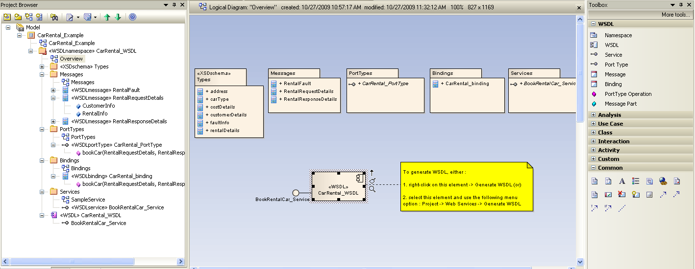
Figure 6 – A look inside a WSDL Package for the CarRental web service
Generating WSDL
Once we’ve defined our Types, Bindings, Ports, Messages, and Services, it’s time to generate WSDL by right-clicking on our WSDL component and choosing Generate WSDL from the context menu. Figure 7 shows the WSDL generation in progress.
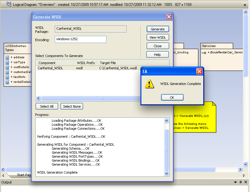
Figure 7- Enterprise Architect generates WSDL automatically
The result of WSDL generation for our Car Rental component can be seen in Figure 8.
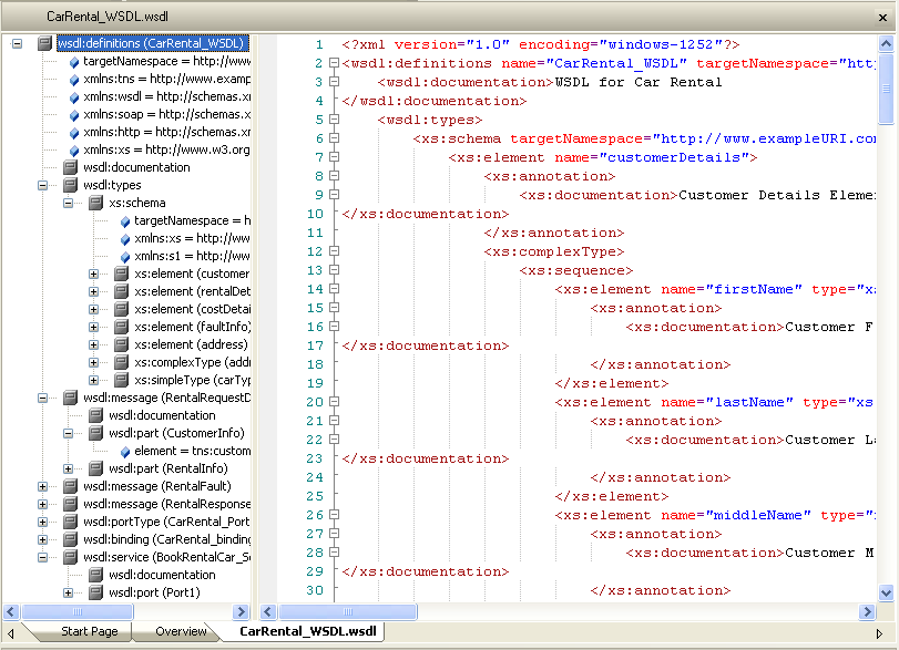
Figure 8 - We’ve successfully generated WSDL for the Car Rental component
Web Service Orchestration using BPEL
The term “orchestration” is often used to describe implementing a business process by using a number of web services in a collaborative way. We’ll use BPEL to orchestrate web services, and BPMN to model BPEL.
Note that it’s possible to draw BPMN (Business Process Modeling Notation) diagrams to model business processes without generating BPEL (Business Process Execution Language). And, you can model BPEL using other graphical notations besides BPMN. But one of the more interesting strategies, which we’re following in this roadmap, involves using BPMN to model BPEL processes[5].
Figure 9 shows the roadmap basic steps for using BPMN to model BPEL.
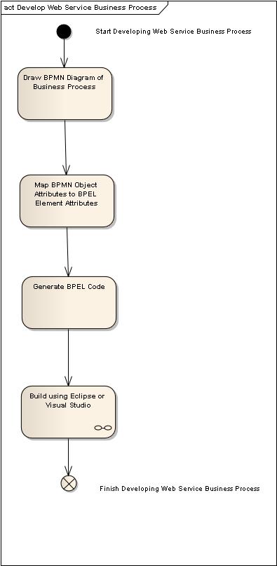
Figure 9 – Roadmap: We use BPMN to model BPEL, then generate BPEL code
A Quick Overview of BPEL
BPEL is short for WS-BPEL, which is short for Web Services Business Process Execution Language. You can use BPEL to build web services, to write programs that call web services, and to describe high-level business processes that make use of web services.
BPEL business processes are often used to implement business-to-business (B2B) transactions where one business provides a web service and another business uses it. Our car rental example in this book is an example of this sort of B2B transaction.
BPEL is sometimes referred to as an orchestration language because it supports complex orchestrations (sequences of messages being exchanged) of multiple service applications. Orchestration refers to the central control of the behavior of a distributed system as opposed to choreography, which refers to a distributed system that operates without centralized control.
There is (intentionally) no standard graphical notation for BPEL, and as a result, some vendors have invented their own notations. However, many people use BPMN (Business Process Modeling Notation) as a graphical front-end to capture BPEL process descriptions.
Modeling BPEL Processes with BPMN

Figure 10 – BPMN diagrams show activities, gateways, messages, pools, and events
Figure 10 shows a BPMN diagram for our BPEL Car Rental Process. The process begins with a Start Event: a Request is received from the Customer. If the customer is of legal age to rent the vehicle, a (B2B) web service is used to check the Customer’s credit card. If the card is valid, another web service is used to rent the vehicle, and a “Success” message is sent. If either the age or credit card checks fail, a “No” message is sent back to the customer.
Mapping BPMN to BPEL
Once we’ve defined our activities, gateways, and events on our BPMN diagram, we can specify additional BPEL details as attributes on our BPMN elements. In Figure 11, we’re defining that the CheckCreditCard activity will be implemented as a web service, and will take a “request” message and generate a “result” response.

Figure 11 – Mapping BPMN to BPEL for interfacing to the creditCardChecker web service
Generating BPEL Code
Finally, after we’ve specified our BPEL Process and validated the model, Enterprise Architect will generate the BPEL code to accomplish our business process.
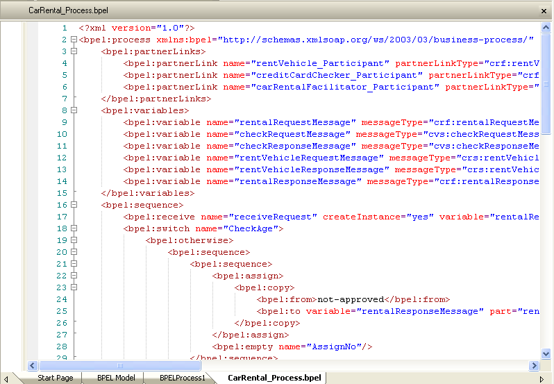
Figure 12 – We’ve successfully orchestrated our web services using BPEL
Business Processes must satisfy Business Rules
Even in a service-oriented system, not all business processes can be implemented by orchestrating web services. Some business processes will involve user interfaces, and some will be focused on enforcing business rules. We won’t discuss GUI-based software use cases in this article, but we will spend a fair amount of time discussing some new ways to implement those processes that are focused on enforcing business rules.
In this section, we’ll introduce you to the unique capabilities of Enterprise Architect’s Business Rule Composer. Starting from the domain model (fact model) and the requirements that we’ll presented earlier, we’ll take you through the process of creating Activity Diagrams for Business Processes, stereotyping Actions as RuleTasks, and finally, linking the business rules to the rule tasks in preparation for Behavioral Code Generation.
Figure 13 shows our roadmap for business-rule-centric scenarios.

Figure 13 – Roadmap: Developing “business-rule-centric” scenarios using EA’s Business Rule Composer
Behavioral Code Generation – a quantum leap in tools capability
One of the common themes of all of our ICONIX Process Roadmaps is that they all get you to code. We’ve always believed that processes that only get you halfway to code (or less) are much better in theory than they are in practice (because in practice, programmers tend to ignore them). Enterprise Architect, since it’s early days, has excelled at “code engineering” (forward and reverse engineering for a wide range of languages, powered by customizable code generation templates). But those already strong capabilities have recently taken a quantum leap in power with the introduction of behavioral code generation from activity diagrams, state diagrams and sequence diagrams. Behavioral code generation is a major advancement over generation of “class headers” (which has been the de-facto meaning of “code generation” for more than a decade).
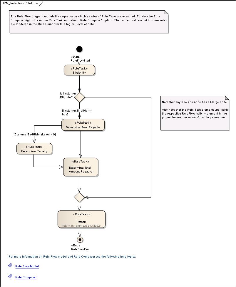
Figure 14 – RuleFlow diagram for processing a car rental application
Let’s take a look at how we’re going to process an application for our Car Rental System. The first thing we need to do is to create a RuleFlow diagram – in this case ProcessApplication (Figure 14). We’ll create this diagram “inside” of a class in the Fact Model, just as if we were creating an Operation on that class, since that is, in effect, what we’re doing. The RuleFlow diagram contains RuleTask actions. Each RuleTask satisfies one or more business rules with some conditional logic.
Linking Business Rules to RuleTasks
What we’d now like to do, is to specify the conditional logic for each of these RuleTasks, while associating each piece of logic with the specific Business Rules that we’re enforcing. As you might have guessed by now, that’s where the Business Rule Composer comes into play. Once we’ve completely specified each RuleTask, we’d like Enterprise Architect to generate 100% complete code for the entire RuleFlow (Activity Diagram). Using Behavioral Code Generation, that’s exactly what we’ll do.
Figure 15 shows the Business Rule Composer for the “Eligibility” RuleTask.

Figure 15 – Specifying conditional logic for Eligibility using the Business Rule Composer
There are 2 sections on the Rule Composer screen. The top panel shows the Business Rules that we’re satisfying within this Eligiblity RuleTask; the lower section (in this case a Decision Table) has 3 parts: a Condition section to model condition variables, an Action section to model action variables, and a Rule Bind section to link the rule in the rule table.
Generate Behavioral Code from Activity Diagrams
Code generation turns out to be very simple (and yields astonishing results) once all the preliminary work has been done. Simply right-click on the Fact Model Class in the Project Browser and select “Generate Code”…and…Voila! No programming required!
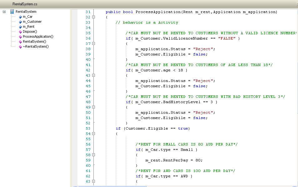
Figure 16 – Enterprise Architect automatically generates complete behavioral logic for the entire rule flow
It’s worth examining the code shown in Figure 16 quite carefully. Here are a few points worth noting:
- The entire RuleFlow diagram is code generated as if it were a single class Operation on the FactModel Class
- Each RuleTask is expanded in-turn
- Within each RuleTask, the Business Rules are automatically propagated forward into the code as comments
- Attribute and Operation names are taken directly from the Rule Composer
- No manual programming intervention is required
It doesn’t take a whole lot of imagination to see that this capability can be a real “game-changer”. Many organizations have thousands of business rules to implement, and “errors in translation” between Subject Matter Experts, Business Analysts, and Programmers are the norm, not the exception. Many of those errors can be eliminated using Behavioral Code Generation and the Business Rule Composer.
Integration with IDEs – keeping model and code synchronized
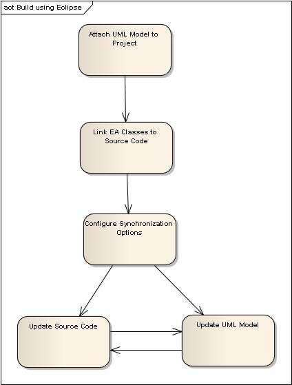
Figure 17 – Roadmap: Keeping models synchronized with code is accomplished with MDG Integration
Since well before UML even existed, one of the biggest issues with modeling software has been keeping the model and the source code synchronized. The typical experience used to be that UML models were most useful in getting the first release of software completed, but after the initial release, the code would evolve independently in a development environment, and the UML model would rapidly grow obsolete.
With the evolution of agile methodologies, this situation often led to projects abandoning UML modeling entirely, as agile methods specify many frequent releases of the software, and getting to the first release became a smaller and smaller percentage of solving the overall problem.
You can beat this problem entirely by using Sparx MDG Integration for Visual Studio and for Eclipse, both of which are included in the EA Business and Software Engineering Edition.
Conclusion
Most SOA systems will contain a mix of 3 different kinds of scenarios:
1) Scenarios that use web services
2) Scenarios that enforce business rules
3) User interface scenarios
Our SOA roadmap takes all these different types of scenarios into account. We use WSDL, BPMN, and BPEL for web-service-centric scenarios, we use the Sparx Behavioral Code Generation and Business Rule Composer capabilities for business-rule-centric scenarios, and we use normal use cases where there are users and systems interacting.
We hope you find the roadmap useful in your development efforts. For more information visit ICONIX on the web at www.iconixsw.com, or contact us at This email address is being protected from spambots. You need JavaScript enabled to view it. .
[1] “Realizing Business Value from an Integrated Service-Oriented Architecture System in a Multivendor World” – IBM Global Technology Services, April 2008
[2] These now include roadmaps for Embedded Systems, Testing (aka Design-Driven Testing), Algorithm Intensive Development, and Business Modeling, in addition to ICONIX Process for Software (the original “Use Case Driven ICONIX Process”). See www.iconixsw.com for more details.
[3] See “Use Case Driven Object Modeling with UML – Theory and Practice” by Doug Rosenberg and Matt Stephens
[4] Wikipedia: Web_Services_Description_Language
[5] We found “Using BPMN to model a BPEL Process” by Stephen A. White, IBM Corporation, to be a very useful article.
ICONIX Process for Embedded Systems - A roadmap for embedded system development using SysML
Doug Rosenberg, ICONIX
At ICONIX, we’ve had pretty good success when we defined an unambiguous development process, and presented that development process in “roadmap” form. We’ve developed process roadmapsfor use case driven software development, business modeling, design-driven testing, and algorithm-intensive software design. In this article we’re going to do it again, this time using SysML to describe embedded systems that involve a combination of hardware and software.
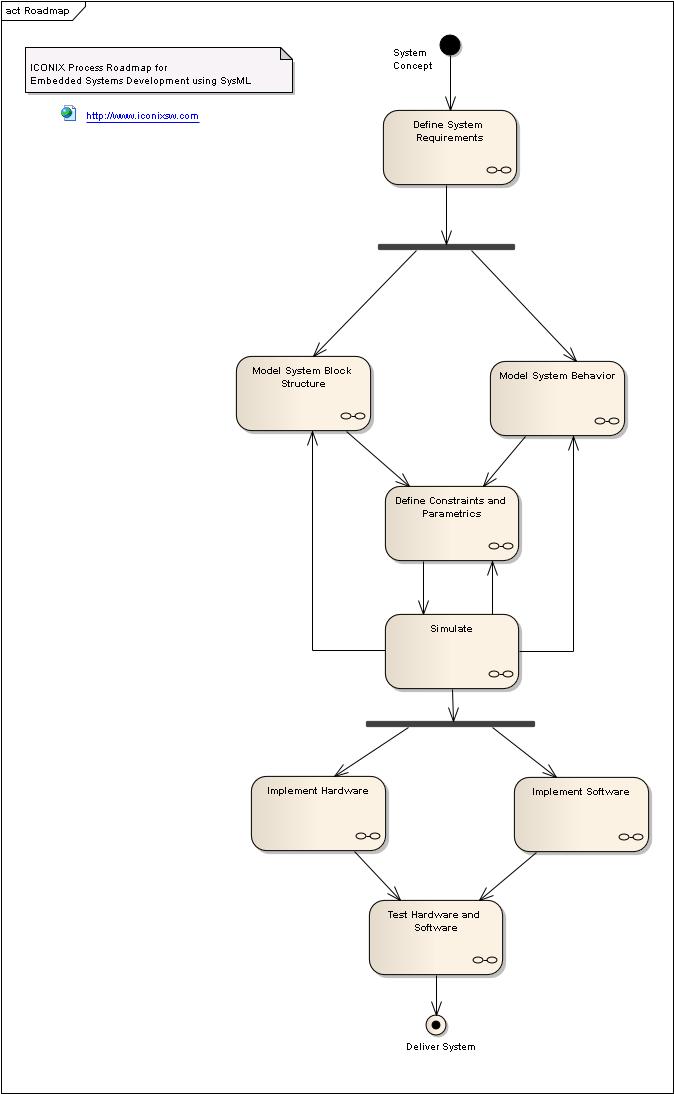
Figure 1 – ICONIX Process Roadmap for Embedded Systems Development
Figure 1 shows the top level roadmap for ICONIX Process for Embedded Systems. As you can see, our roadmap starts off by defining requirements, proceeds through modeling of system behavior and block structure, and then through definition of constraints and parametrics, simulation, and then implementation in both hardware and software. We’ll illustrate our roadmap using an example model, developed by Sam Mancarella from Sparx Systems, that describes an Audio Player.
We’ll also introduce you to some unique capabilities of Enterprise Architect Systems Engineering edition, which supports advanced features such as executable code generation from UML models (including support for hardware description languages such as Verilog and VHDL), executable SysML Parametric diagrams and advanced scripting.
Each of these capabilities, taken standalone, adds a significant amount of “horsepower” to a systems engineering effort. We’ll combine these capabilities into a single process roadmap that’s greater than the sum of its parts.
The Four Pillars of SysML - Requirements, Structure, Behavior, and Parametrics
Our Embedded System Development Process Roadmap is built around producing a SysML model that is organized into four sections. These parts of the overall system model (Requirements, Structure, Behavior, and Parametrics) are sometimes referred to as “The Four Pillars of SysML”.[1] As with UML, Packages are used to organize the model.
SysML Pillar #1: Requirements
Requirements are generally categorized as Functional Requirements, which represent capabilities of a system, and Non-Functional Requirements, which cover such areas as Performance and Reliability. You can organize Requirements into hierarchies on requirement diagrams (see Figure 2).
EA supports allocation of requirements to other elements using a simple drag-and-drop, and automatic generation of traceability matrices.
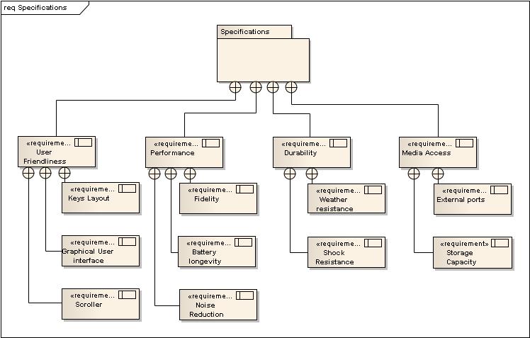
Figure 2 – Requirements for the Audio Player include Performance, Durability and User Friendliness
Figure 3 shows the steps for Requirements definition from our process roadmap. Note that allocation of Requirements to System Elements is really an ongoing process as the model is developed, and largely occurs within other roadmap activities.
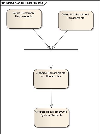
Figure 3 – Roadmap: Define System Requirements
SysML Pillar #2: Structure
Blocks can be used to represent hardware, software, or just about anything else. Block definition diagrams represent system structure. Internal block diagrams describe the internals of a block such as parts, ports, and connectors.
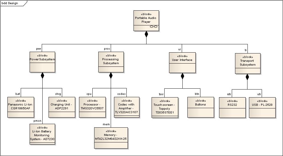
Figure 4 – Block Structure for the Audio Player
Figure 5 shows how our process roadmap approaches defining system structure.
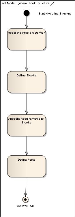
Figure 5 – Roadmap: Model System Structure
If you think of a Block as an electronic circuit (one of many things that a Block can describe), the Ports define the input/output signals to and from the circuit. SysML allows you to describe the I/O signals and transformations in great detail, and EA contains a built-in simulator that allows you to plot the output graphically.
SysML Pillar #3: Behavior
SysML provides four main constructs to represent different aspects of system behavior; use cases, activity diagrams, sequence diagrams, and state machines. As shown in Figure 6, our roadmap shows two parallel branches for modeling system behavior.
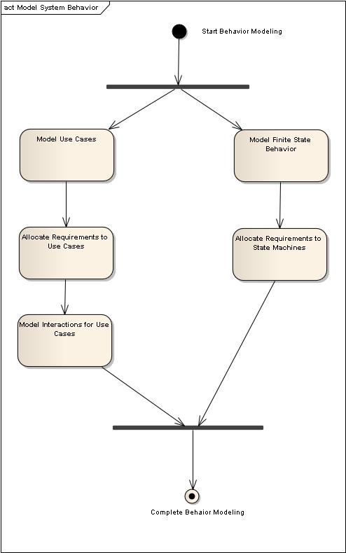
Figure 6 – Roadmap: Model System Behavior
One branch starts with use cases[2], which describe scenarios of how users will interact with the system. Use cases generally consist of a “sunny-day” part, which describes a typical success-path for the scenario, and multiple “rainy-day” parts which describe unusual conditions, exceptions, failures, etc. Figure 7 shows a Use Case Diagram which organizes the scenarios in listening to the Audio Player.
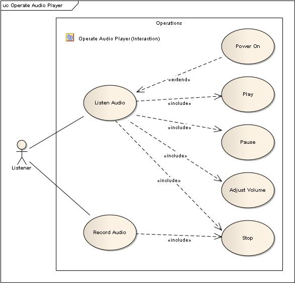
Figure 7 – Audio Player Use Cases
Use cases are typically detailed on Interaction (Sequence) Diagrams, which can also be drawn at a higher level. Figure 8 shows Interactions between the Listener and the Audio Player. Note the use of parallel paths on the Interaction Diagram.
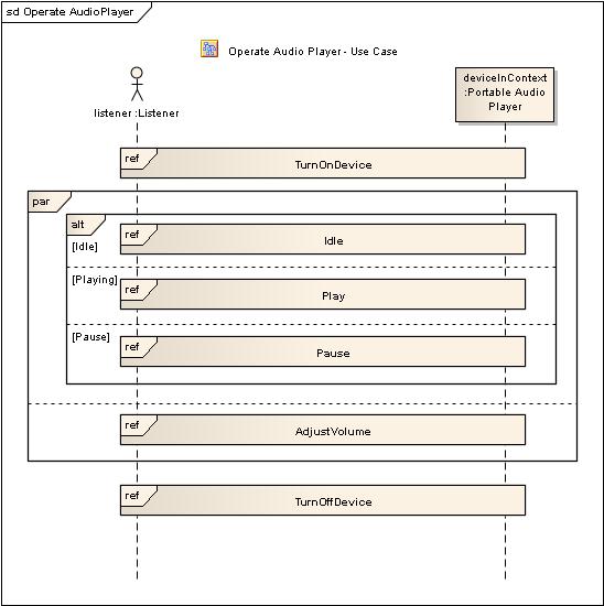
Figure 8 – Audio Player Interactions, showing interactions occurring in parallel
The other branch on the roadmap involves defining event-driven, finite-state behavior of some part of a system using state machines. As a simple example, Figure 9 shows some finite state behavior associated with Playlist Maintenance for our Audio Player.
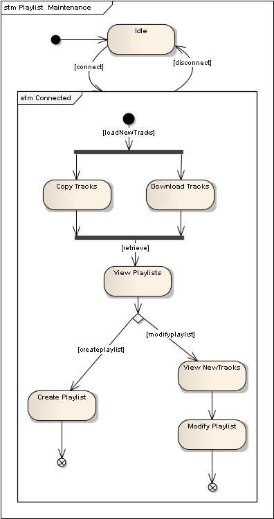
Figure 9 – Finite State Behavior for Playlist Maintenance
One of EA’s unique capabilities is the ability to generate functional (algorithmic) code from state machines. As you’ll see, these state machines can be realized in software or in hardware using Hardware Description Languages (HDLs).
Requirements are allocated to both use cases and states.
SysML Pillar #4: Parametrics
Parametrics allow us to define detailed characteristics, physical laws, and constraints on system blocks that allow us to simulate how a system will behave, then make engineering tradeoffs, and re-simulate until our design meets the specified requirements.
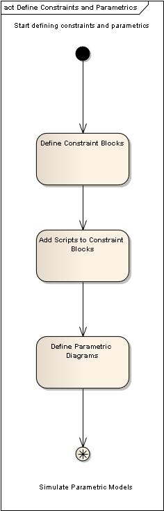
Figure 10 – Roadmap: Define Constraints and Parametrics
Our roadmap provides two high-level activities in this area; the first to define constraint blocks and parametric diagrams (shown in Figure 10 and illustrated in Figures 11 and 12), and the second to configure and execute the simulations (shown in Figure 13).
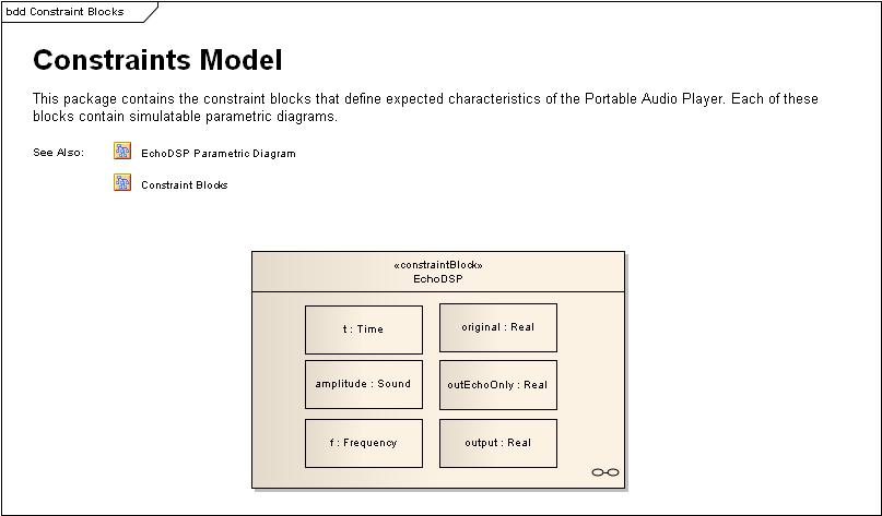
Figure 11 – Constraint Blocks for the Audio Player’s “Echo” signal processing function
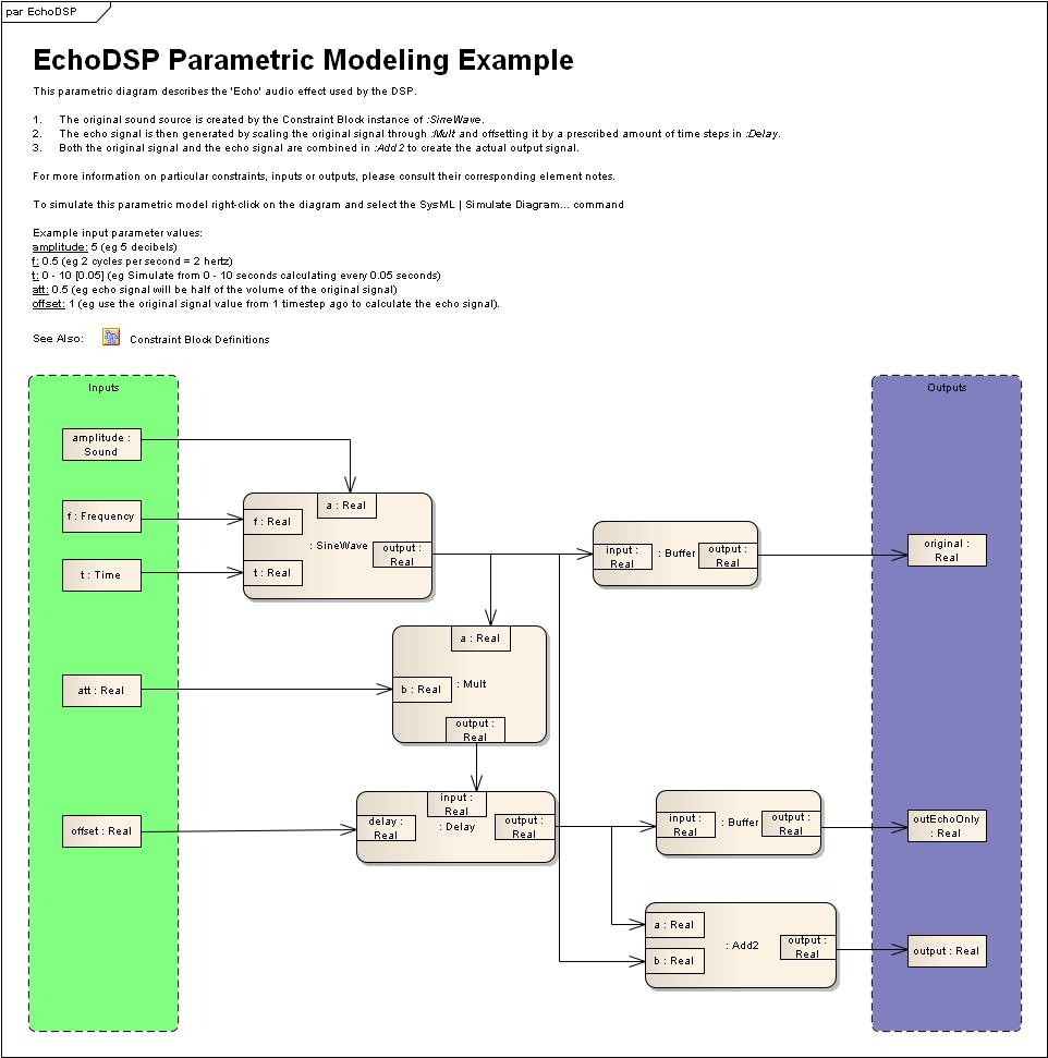
Figure 12 – Parametric model for the Audio Player’s “Echo” signal processing function
Simulation
The ability to configure and execute simulations within EA, eliminating the need to export the model to external simulation software, is one of the unique capabilities of the Sparx SysML solution.
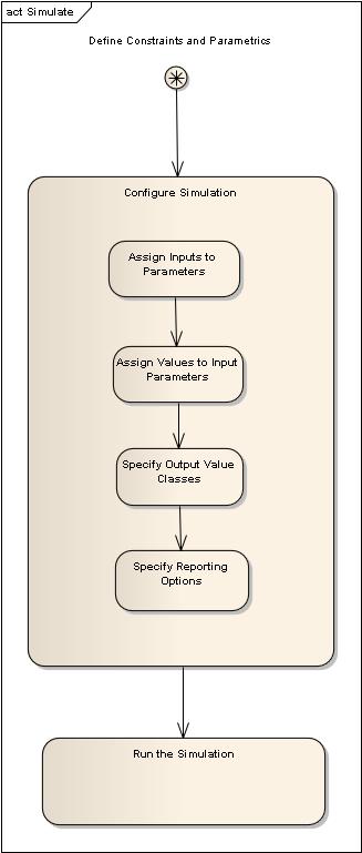
Figure 13 – Roadmap: Simulate
EA’s built-in support for scripting and graphical display of simulation results tightens the feedback loop on making engineering tradeoffs in the model to rapidly ensure that all system requirements are met.
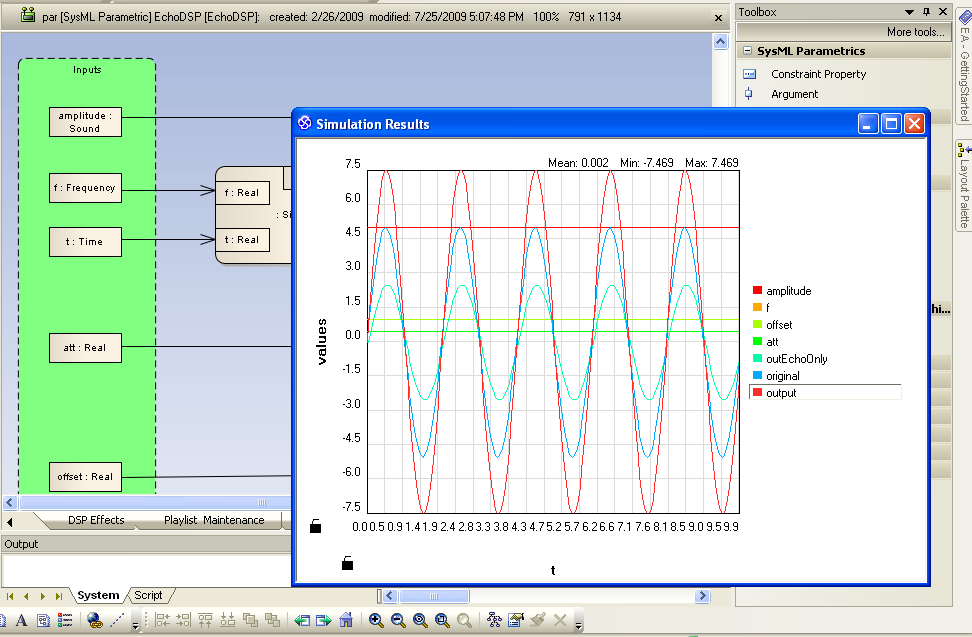
Figure 14 – Results of simulating the “Echo” function are displayed within Enterprise Architect and do not require the use of external simulation software.
Implement Hardware
Hardware Description Languages allow the specification of electronic circuits in a software-like representation. According to Wikipedia[3]:
In electronics, a hardware description language or HDL is any language from a class of computer languages and/or programming languages for formal description of electronic circuits, and more specifically, digital logic. It can describe the circuit's operation, its design and organization, and tests to verify its operation by means of simulation.
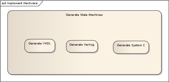
EA’s long-proven ability to generate code has been extended to support code generation in VHDL, Verilog, and System C in the Systems Engineering Edition. While code generation is independent of SysML usage, from a process roadmap standpoint, this means we can drive both hardware and software implementation from our SysML model. Once code is generated in an HDL, it’s possible to “compile to silicon” to realize the hardware solution on a chip. This process is shown in Figures 16 and 17, which show how a playback controller can be generated in VHDL.
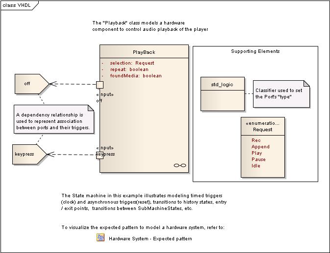
Figure 16 – SysML model of hardware component for controlling audio playback
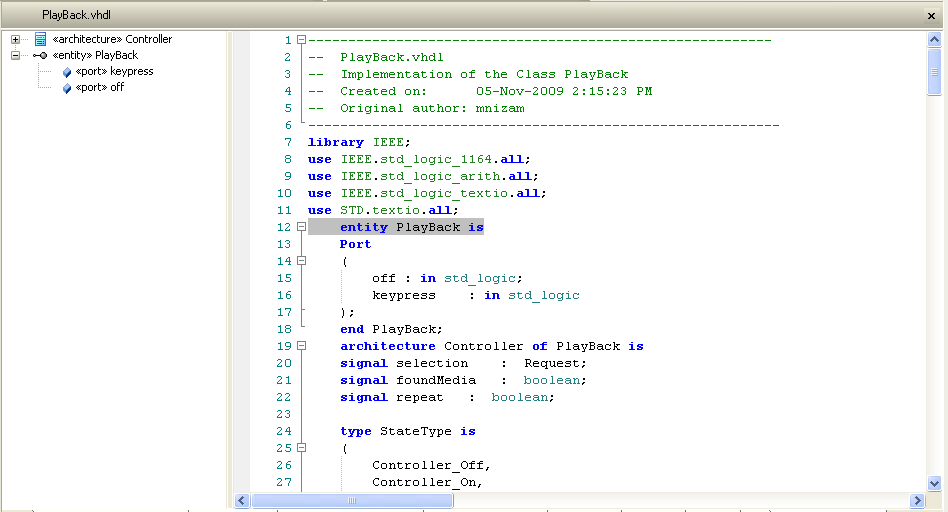
Figure 17 – Audio playback controller, generated in VHDL
Implement Software
Software implementations can leverage a variety of powerful capabilities that are included with the System Engineering Edition of EA. Two of the more important and unique capabilities are:
- The ability to generate functional (algorithmic) code from behavioral models (state machines, activity diagrams, and interaction diagrams)
- The ability to integrate EA models into development environments such as Eclipse and Visual Studio.
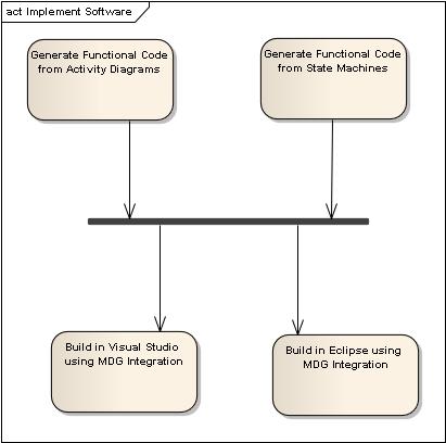
Figure 18 shows a high-level look at the Software Implementation activity from the roadmap.
Figure 18 – Roadmap: Implement Software
Conclusion
This article has presented a high-level overview of ICONIX Process for Embedded Systems, which leverages Enterprise Architect System Engineering Edition to build hardware/software models that are structured around the “four pillars of SysML”. We’ve illustrated our process roadmap with diagrams from Sam Mancarella’s Audio Player Example.
This topic will soon be expanded into an “eBook”: Embedded Systems Development using SysML and Enterprise Architect.
For more information, visit ICONIX on the web at www.iconixsw.com, or contact us at This email address is being protected from spambots. You need JavaScript enabled to view it.
[1] OMG Systems Modeling Language Tutorial, INCOSE 2008
[2] See “Use Case Driven Object Modeling with UML: Theory and Practice” by Doug Rosenberg and Matt Stephens for a lot more information about use cases.
[3] http://en.wikipedia.org/wiki/Hardware_description_languages
Automatic Unit Test Generation from Reverse Engineered Code using the Agile/ICONIX add-in
(Article originally published in SDJournal)
This article presents an easy step-by-step formula that will get from code to a comprehensive test plan, that includes a complete set of unit test code, using the free Agile/ICONIX add-in for EA.
Here are the 6 steps that we’ll follow:
1)Reverse engineer some code
2)Generate tests from Class Operations
3)Add test scenarios in EA’s testing view
4)Transform the test cases to test classes
5)Generate the unit test code from the test classes
6)Generate a test plan report
We’ll illustrate this approach one step at a time in this article, using some reverse engineered ActionScript (Flex) code from the example project we built while writing Design Driven Testing.